“Cheap” and “Laser Cutter” are not words that are normally seen together; the CO2 laser tubes they use are often to blame for this. Cooling systems, high-voltage power supplies, and flying-mirror assemblies don’t help.
This project tries to circumvent this through the use of a 40W DDPS fiber-coupled laser diode. This laser module is the size of a deck of cards, but it is capable of outputting enough power to cut through “most” materials. “Most”, since its output wavelength differs from the standard; 1um is better absorbed by metals than plastics.
I decided to put this concept to work after I received funding from ProjX, an organization at MIT that funds DIY projects. I had access to a waterjet & lasercutter, so most of the parts on this machine were designed to be cut out of flat sheet stock. The remainder of the structural elements were primarily 80/20 and acrylic.
The machine was built around the CoreXY motion platform (made by Ilan E. Moyer). CoreXY allows one to move a carriage in X-Y space with only two stationary motors. This makes for a lighter gantry that can accelerate faster – which is essential for proper cutting!
Solidworks was used to create the design. “Cut once, measure twice” is even more important when 40W of laser power are involved.
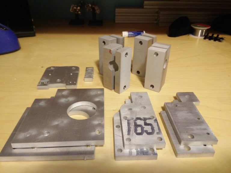
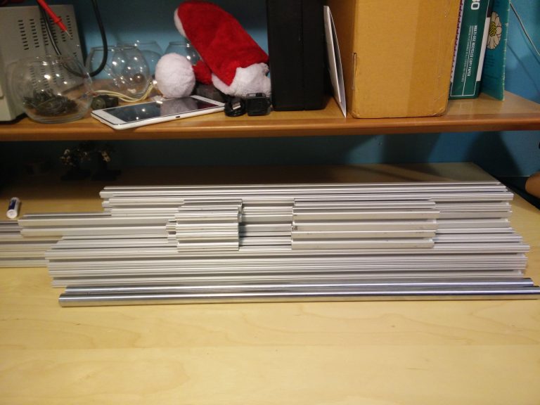
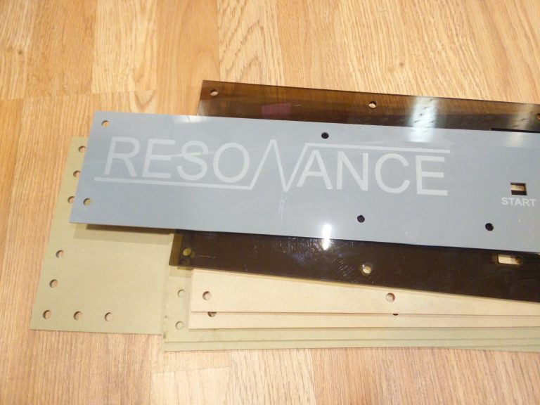
All of the aluminum parts were cut out first. The aluminum plate and 80/20 were taken from scrap piles at MIT. Acrylic plates were then cut using a laser cutter.
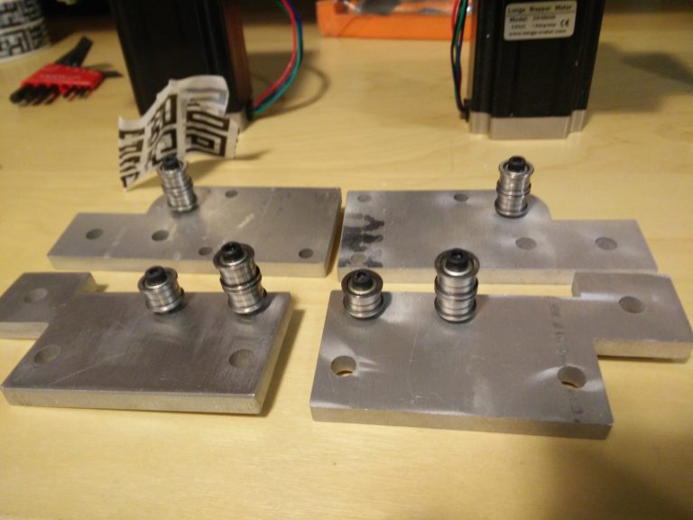
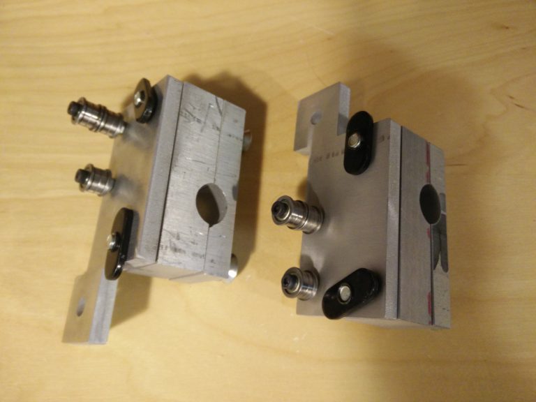
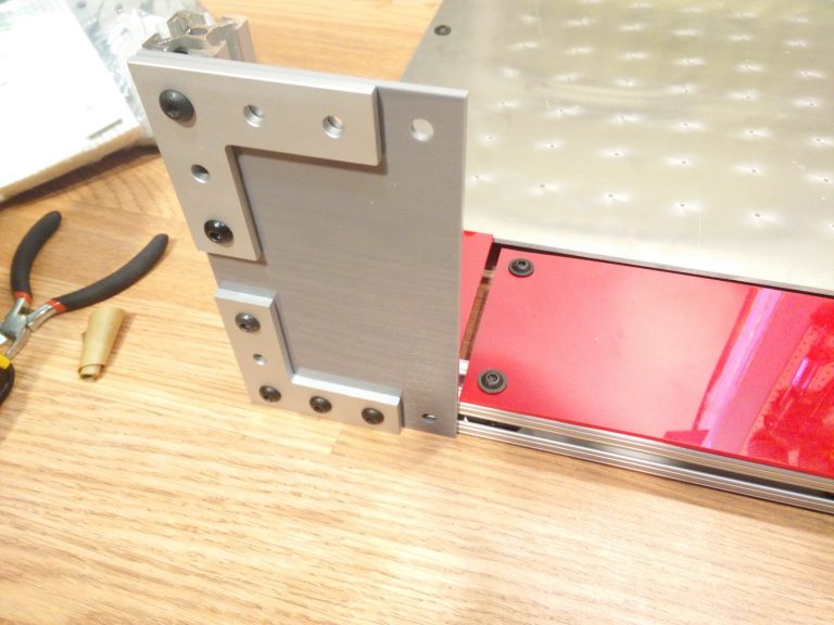
Some basic small assemblies were built first.
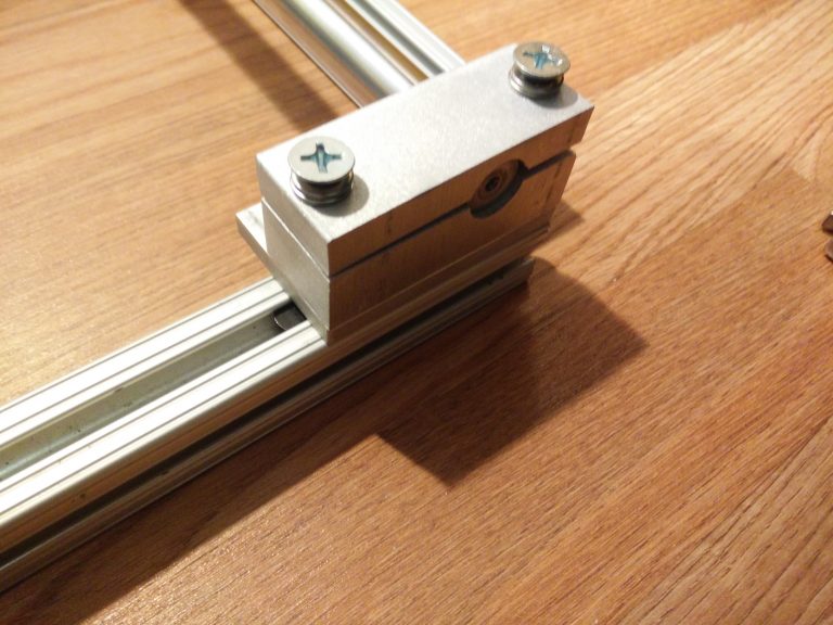
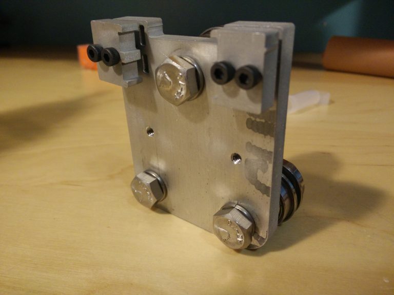
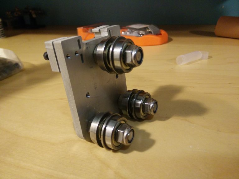
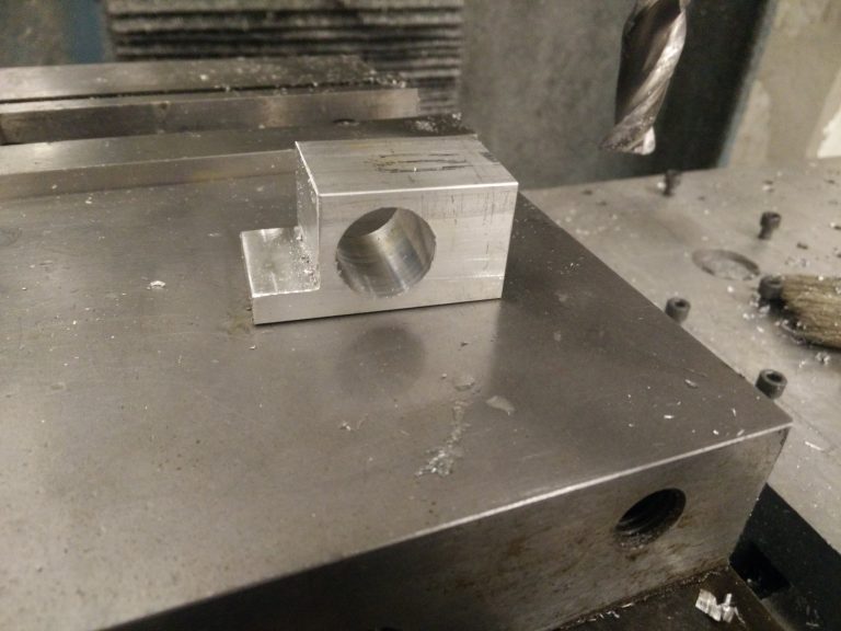
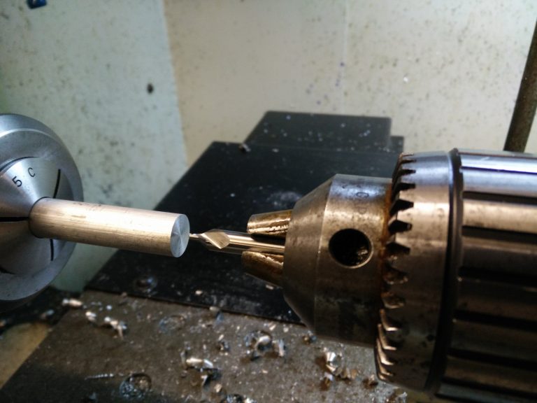
This 16MM rail mount was one of the few parts that was manually machined. It predictably took the most time to create…
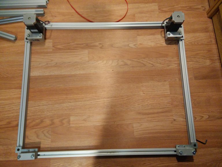
The X-Y frame was the first “laser-cutter-esque” assembly to come together.

Round rails with linear bearings were used for the Y axis. These were scrounged from an old plotter.
The X axis carriage was designed to ride on a single beam of 80/20. Flanged bearings were positioned in a fashion that allowed them to ride in the 80/20’s grooves.
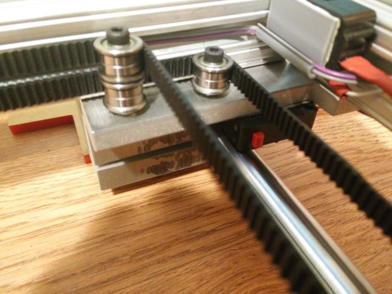
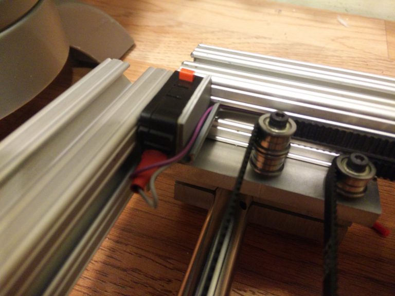
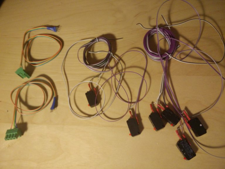
Belts & limit/door switches were added; they held the system together better than expected!
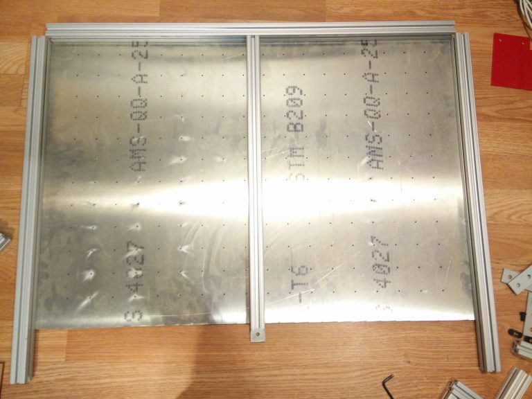
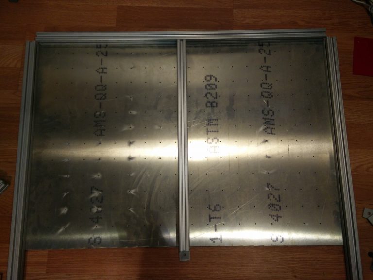
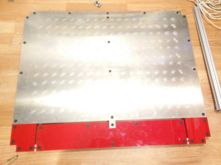
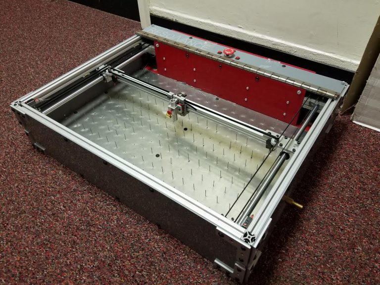
A large sheet of aluminum with ~200 small holes pierced in it was used as the bed of the machine. Why holes? Every hole had an unused pop rivet placed in it. This effectively made it into a pin board.
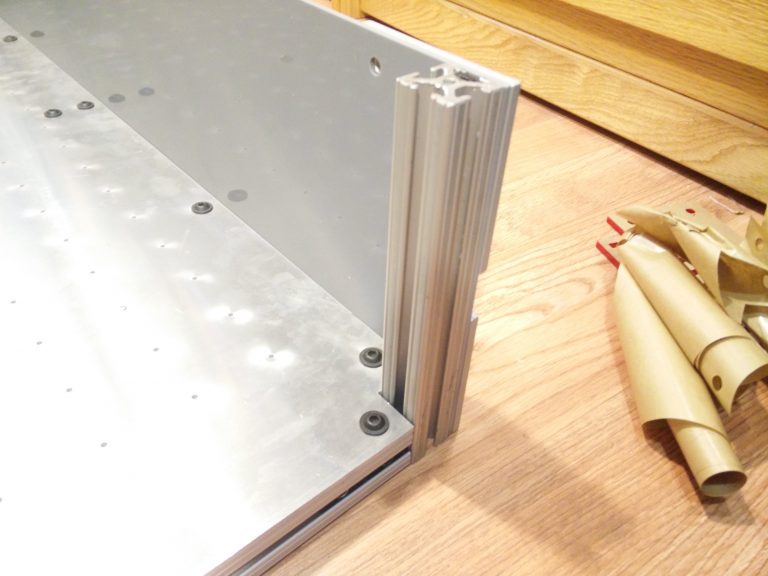
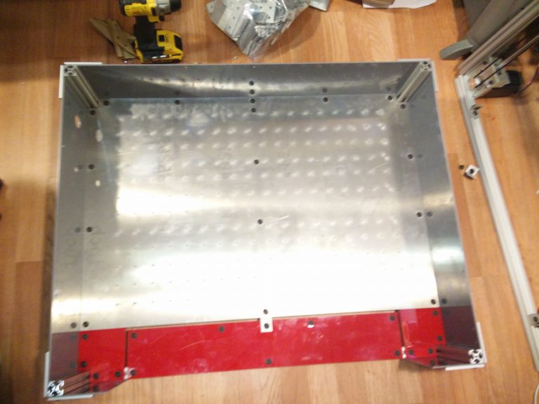
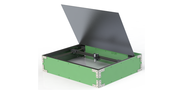
A box is starting to take shape.
The carriage shown above is useless without a cutting head. This part contains two precision IR-rated lenses designed to converge the rays emitted by the fiber laser into a micron-scale pinhead on the workpiece. A good deal of lathe/mill work was needed for this part.
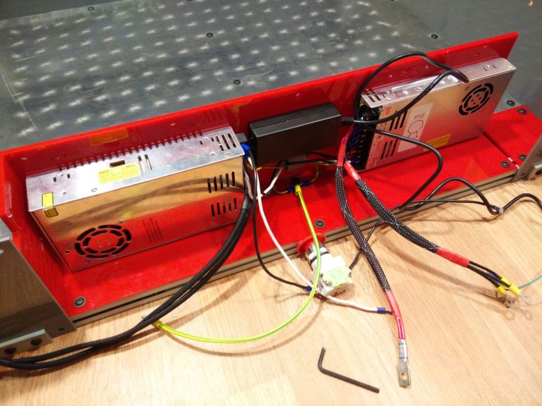
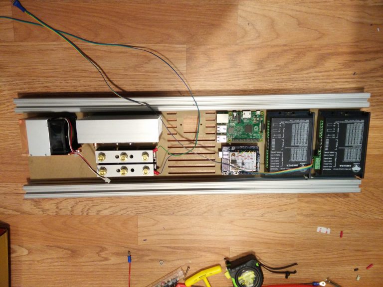
The electronics were designed to be hidden in a small box at the back of the machine. An onboard RPi2 is the brains behind the machine. A copy of LaserWeb3 lets one operate the laser cutter entirely through a browser interface. Handy!
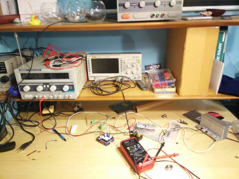
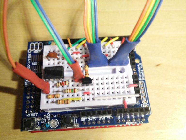
The mechanical portion of the machine is now finished; all that needs to be added is a laser driver. Providing 50A of perfectly smoothed current with PWM capabilities is not as easy as hoped, but progress is being made. This post will be updated once the machine starts cutting!
Update: I have a laser driver! It won’t be long until this makes its first cuts.